A PT100 changes its resistance by 0.385 ohms per degree. That is not much. The cable to the sensor can add more than that on its own.
Put that tiny change in a panel full of contactors and frequency drives, and you have a problem. You need to see a fraction of an ohm, reliably, next to equipment that throws electrical noise around all day.
As an electrician I pulled the cable to PT100s and landed it on terminals. What happened to the signal after that was someone else’s job. This post is me opening that box.
The classic answer is a Wheatstone bridge. Modern transmitters often use a precise current source and a good converter instead. But the bridge is the clearest way to see the actual problem, so that is where we start.
Temperature becomes resistance
Metal resists current more when it gets warm. Platinum does this in a very even and repeatable way, which is why it is used for sensors. The rule is the same one you use for copper wire.
For a PT100, R₁ is 100 Ω at t₁ = 0 °C, and α is 0.00385 per degree. So at 100 °C the sensor measures 100 · (1 + 0.385) = 138.5 Ω. At 20 °C it measures 107.7 Ω.
Now the cable. Say the sensor sits 10 meters away on a 0.5 mm² copper pair. That is 20 meters of copper there and back, which is about 0.7 Ω. With a plain two-wire connection, the meter reads that as almost 2 °C extra. That is why real installs use three or four wires. It is also a good picture of how small the signal is.
The bridge is two voltage dividers
A voltage divider is two resistors in series across a supply. The voltage at the middle depends on the ratio between them.
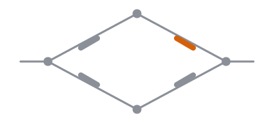
A Wheatstone bridge is just two of these side by side, on the same supply. Here are the values I use:
- Supply: 3.3 V.
- Left divider: R1 = 2.2 kΩ on top, R2 = 100 Ω at the bottom. The middle point is A.
- Right divider: R3 = 2.2 kΩ on top, the PT100 at the bottom. The middle point is B.
- The output is the voltage from A to B: U = B − A.
At 0 °C the PT100 is exactly 100 Ω. Both sides then have the same ratio, so A and B sit at the same voltage. The output is zero. We say the bridge is balanced.
When the sensor warms up, its resistance grows. B rises, A stays put, and the output moves away from zero. That difference is the whole signal. At 100 °C it is 52.0 mV. At 200 °C it is 102 mV, and at −50 °C it goes negative, to −26.6 mV.
Why measure a difference, and not just the voltage at B? Because B is about 0.14 V at 0 °C and only climbs 52 mV over the first 100 degrees. The bridge removes the big, boring part, so the converter can spend all its steps on the part that changes.
Why 2.2 kΩ and not 100 Ω everywhere
Textbook bridges often use the same value in all four arms. Try that with 100 Ω and 5 V. Each side is then 200 Ω, so 25 mA runs through the sensor.
The sensor turns that current into heat: 25 mA through 100 Ω is about 60 milliwatts. That is enough to warm the PT100 itself, so it measures its own heat on top of the process. This is called self-heating, and it is a classic trap.
With 2.2 kΩ on top and 3.3 V, the sensor current is about 1.4 mA. The heat in the sensor drops to about 0.2 milliwatts, around 300 times less. The price is a smaller output voltage. That trade comes back to bite us in the converter section.
Play with it here. Drag the temperature, change what is connected to the output, and watch the curve.
Look closely at the curve and the dashed line. The dashed line is straight, with the same slope the curve has at 0 °C. In the simple model used here, the PT100 itself is linear. A real one bends slightly too, about 3 °C at 200 °C. But the point here is the bridge. It is not linear either, because the current through the right side drops a little as the sensor grows. Between 0 and 100 °C the curve stays close to the dashed line. At 200 °C the gap is about 3.4 mV. If your code treats the bridge as a straight line, it reads about 6.5 °C too low up there.
What your meter sees: Thevenin
Your meter does not see two dividers. It sees two terminals, A and B. Thevenin says that anything behind two terminals can be replaced by one voltage source and one resistor in series.
The voltage is easy. It is the output with nothing connected, 52.0 mV at 100 °C. The resistance is what you see looking into A and B with the supply shorted. Then R1 and R2 are in parallel. So are R3 and the PT100. The two pairs are in series.
At 100 °C that gives about 96 Ω + 130 Ω = 226 Ω. So the bridge behaves like a 52 mV battery with 226 Ω in series.
Now connect something. The meter’s own input resistance forms a new voltage divider with those 226 Ω. Ohm’s law decides how much is lost.
- A multimeter has about 10 MΩ of input resistance. The loss is about 1 µV, or 0.002 % of the signal. You will never see it.
- The ADS1115 has about 710 kΩ between its inputs on the ±0.256 V range, according to its datasheet. The loss is about 16 µV, roughly 0.03 °C.
- A 1 kΩ load is another story. The voltage drops from 52.0 to 42.4 mV. If your code still assumes nothing is connected, it reports about 81 °C for water that is boiling.
That is the point of Thevenin here. The bridge is a weak source. Anything you connect must have a much higher resistance than 226 Ω, or it changes the answer.
The converter problem
In my post about 4-20 mA I said the converter layer was the part I had not worked with hands-on. This post closes that gap. The bridge gives us a clean signal of a few tens of millivolts. Now something has to turn it into a number.
An Arduino Uno has a 10-bit ADC. It splits 0 to 5 V into 1024 steps, so each step is 4.9 mV. The bridge moves 52 mV between 0 and 100 °C. That is about 11 steps, or roughly 9 degrees per step. You could tell a freezer from a kettle. Not much more.
And it gets worse. An Arduino analog input measures against ground (GND). Connect B to A0 and you read B, about 0.2 V at 100 °C. You do not read the bridge output at all. To get U = B − A you must read A on one input, B on another, and subtract in code.
Each of those two readings still has 4.9 mV steps. Each one also has its own noise and its own rounding. The difference is still about 11 steps over 100 degrees, now with two sources of error instead of one.
The Arduino tile in the widget above pretends the converter could read U directly. Above 0 °C that is the kind version. Real life has two roundings and two sources of noise, so it is a little worse. Below 0 °C it is the other way round. The tile shows 0, because a plain input can’t read a negative voltage. But A and B are both still positive, so the subtraction in the sketch does give negative values.
The ADS1115 fixes both problems at once:
- It has a differential input. It measures the voltage between AIN0 and AIN1 directly, so B − A is one reading, negative values included.
- It has gain. At gain 16 its range is ±0.256 V, and it splits that into 65536 steps. Each step is 7.8 µV.
Over the same 0 to 100 °C, that is about 6650 steps, or around 66 steps per degree. Compare that to 0.1 step per degree on the Arduino. Same bridge, same signal. The converter is the difference.
Build it yourself
You need:
- An Arduino Uno and an ADS1115 breakout board.
- A PT100, or a 100 Ω trimmer pot as a fake sensor.
- Resistors with 1 % tolerance: two 2.2 kΩ and one 100 Ω.
- A breadboard, some jumper wires and a multimeter.
The bridge runs on the Uno’s 3.3 V pin. The ADS1115 talks to the Uno over I²C, a two-wire bus for chips on the same board. The sketch reads the bridge both ways once per second. It reads A and B on the Uno’s own inputs and subtracts, and it reads B − A on the ADS1115 with gain 16. Both results are printed as raw steps and as temperature. Wiring is in the comments at the top.
The test points are ice water (0 °C), room temperature and boiling water (100 °C). With a trimmer pot, set it to the matching resistance with the multimeter: 100.0, 107.7 and 138.5 Ω.
Here are the numbers. Calculated is the math from this post. Simulated is the same circuit drawn in Multisim, a circuit simulator. Measured is the breadboard. The two last columns say TBD until I have done the work.
| Point | PT100 | Calculated | Simulated | Measured |
|---|---|---|---|---|
| 0 °C | 100.0 Ω | 0.0 mV | TBD | TBD |
| 20 °C | 107.7 Ω | 10.5 mV | TBD | TBD |
| 100 °C | 138.5 Ω | 52.0 mV | TBD | TBD |
Simulation uses perfect parts. It should match the math almost exactly. The breadboard won’t, and I already know two reasons why.
First, resistor tolerance. If R1 is 1 % high, A drops by about 1.4 mV. The bridge is then no longer balanced at 0 °C, and everything reads 2 to 3 degrees off. That is why you calibrate in ice water.
Second, the supply. The output is directly proportional to it. If the Uno’s 3.3 V pin really gives 3.25 V, every reading is 1.5 % low. Measure it and put the real number in the sketch. The same goes for the 5 V pin, which is the reference for the Uno’s own inputs. On USB it often gives 4.7 to 5.0 V, so measure that too and adjust the constant. If the measured column ends up more than a few percent off, I will explain why right here.
In short
- A PT100 changes 0.385 Ω per degree. That is smaller than the error from a short cable.
- The bridge is two voltage dividers. At 0 °C it is balanced, and the imbalance is the signal.
- 2.2 kΩ on top keeps the sensor current near 1.4 mA, so the sensor does not heat itself.
- Seen from the meter, the bridge is 52 mV behind 226 Ω at 100 °C. Load it with 1 kΩ and you lose almost a fifth of the signal.
- A plain Arduino input sees about 11 steps over 100 degrees, and it can’t measure between A and B. The ADS1115 measures the difference directly and sees about 6650.
The sensor is the easy part. The interesting work happens between the sensor and the number.